This article focuses on practical, engineering-level guidance for universal joint shafts (U-joint shafts). It covers definitions, configuration choices, sizing formulas, material and heat-treatment recommendations, assembly and phasing procedures, inspection checklists, common failure modes and finishing/manufacturing tolerances — all written so a designing or maintenance engineer can apply it directly.
What a universal joint shaft is and when to use it
A universal joint shaft transmits torque between non-collinear shafts using one or more universal (Hooke-type) joints. Unlike constant-velocity joints, a basic U-joint allows angular misalignment but produces speed fluctuation when used alone. Use U-joint shafts where:
- Angular misalignment is moderate (typically up to 25–30° per joint for heavy-duty designs).
- Simplicity, cost and ease of maintenance are priorities.
- System can accept speed fluctuation or use paired (double) U-joints to cancel it.
Types and configurations of universal joint shafts
Single vs. double (cardan) U-joint shafts
A single U-joint transmits torque between misaligned shafts but introduces non-uniform angular velocity. A properly phased double U-joint (two U-joints with a center shaft) cancels velocity variations if both joints operate at equal angles and are phased correctly — this is the most common solution in drivetrain applications.
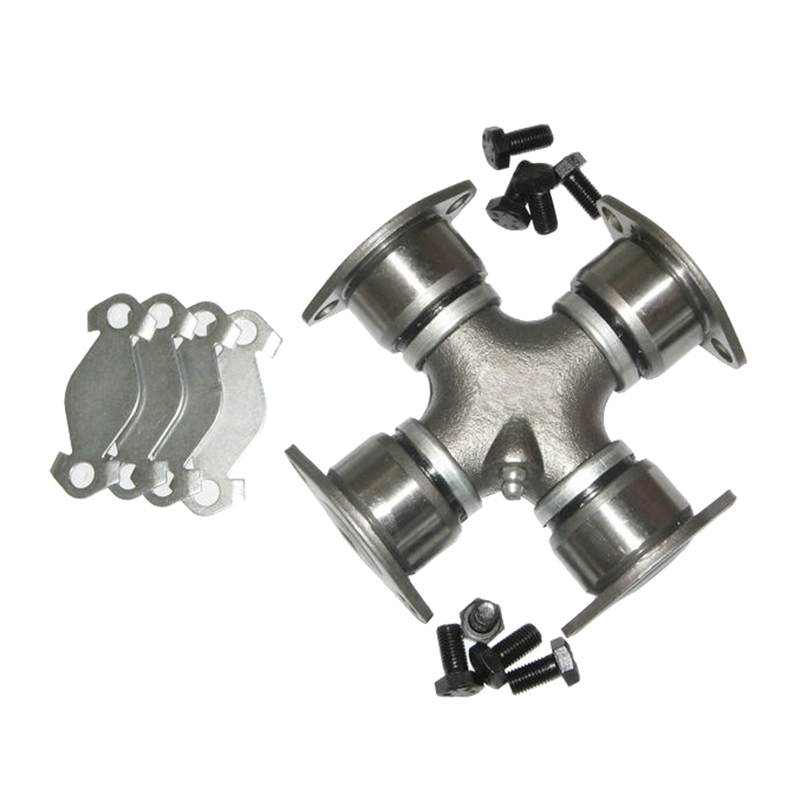
Cross-bearing (four-bolt) vs. tripod and constant-velocity hybrids
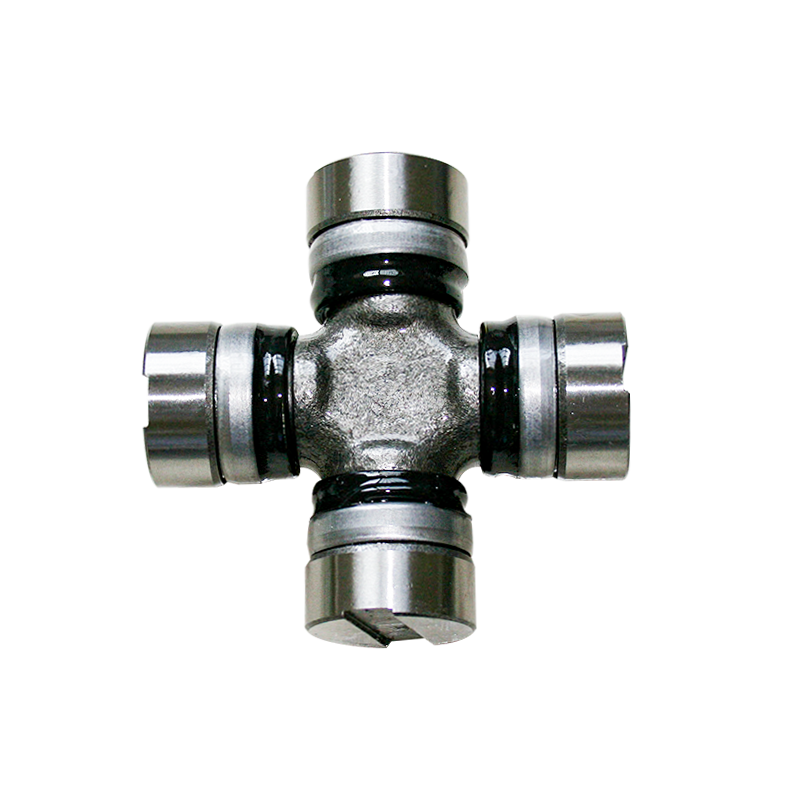
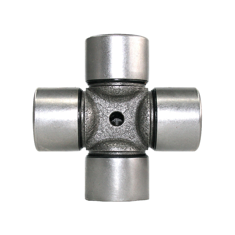
Cross-bearing Joints (with a needle bearing cross) are compact and robust for heavy radial loads. Tripod-style or CV-hybrid joints reduce vibration at higher angles but are more complex and costly. Choose based on required misalignment, duty cycle, lubrication access, and dynamic balancing needs.
Design and sizing principles (practical formulas)
Basic torque and shaft diameter selection
Start with the transmitted torque. If you know horsepower (HP) and shaft speed (RPM):
- Torque (lb·ft) = (HP × 5252) / RPM.
- For metric units: Torque (N·m) = (HP × 745.7) / (2π × RPM/60) — easier to convert HP to kW and use T (N·m) = (kW × 9550) / RPM.
Once torque (T) is known, determine the required shaft section modulus and diameter using allowable shear stress (τ_allow). For a solid circular shaft under torsion:
- Polar moment J = π·d⁴ / 32
- Shear stress τ = T·c / J = (16·T) / (π·d³)
- Rearrange to solve for d: d ≥ ( (16·T) / (π·τ_allow) )^(1/3)
Use a safety factor appropriate for application: typical fatigue/rotating shafts use 1.5–3.0 depending on shock loading and unknown duty cycles. For keyed or splined shafts, account for stress concentrations and reduce allowable stress accordingly.
Material selection, heat treatment and surface finishes
Common materials and treatments for U-joint shafts:
- Medium-carbon steels (AISI 1045/EN C45): good machinability; suitable for moderate loads after stress-relief or surface hardening.
- Alloy steels (4140/42CrMo): preferred for higher torque/fatigue applications; through-hardened or quenched & tempered to > 800–1000 MPa tensile as needed.
- Case hardening (carburize or nitriding) for splines or journals to improve wear while retaining a tough core.
- Surface finish: Ra ≤ 0.8 µm recommended at bearing journals; polished bearing seats extend needle bearing life.
Assembly, phasing, balancing and runout limits
Phasing rules (to avoid vibration)
When using two U-joints in series, both joints must have equal operating angles and be phased 180° (yokes oriented) so that the driven shaft's velocity fluctuation is cancelled. Practically:
- Lay out yoke ears visually and mark them; install so flange/yoke marks align in the specified phase.
- Confirm equal angles with an angle gauge; unequal angles produce residual vibration proportional to the difference.
Dynamic balancing and runout
Shafts with U-joints and center sections should be dynamically balanced if operating speeds exceed typical engine idle or if vibration tolerance is low. Target runout and balance tolerances:
- Total indicated runout (TIR) at bearing journals: ≤ 0.05 mm for high-speed drivetrains.
- Dynamic balancing to ISO 1940/1 Grade G16 or better for automotive applications; heavier rotating equipment may require G6.3–G2.5.
Inspection, lubrication & maintenance checklist
Regular checks dramatically extend life. Use the following practical checklist during scheduled maintenance:
- Visual inspection of yoke reliefs, cross trunnions and seals for scoring, corrosion or grease leakage.
- Check bearing play: axial or radial play beyond manufacturer's tolerance indicates bearing wear; measure with dial indicator.
- Grease intervals: re-lube needle bearings per duty cycle (typical: every 50–200 hours) using compatible NLGI grade and bearing grease.
- Check for noise and vibration under load — sudden onset suggests bearing collapse, cross failure or misphasing.
Common failure modes and root causes
Recognizing the failure mode helps prescribe the correct fix:
- Premature needle bearing wear — typically from insufficient lubrication, contaminated grease, or misalignment.
- Cross/trunnion fracture — high shock loads or incorrect material/heat-treatment; examine fracture surface for fatigue vs. overload signatures.
- U-joint yoke deformation — excessive bending moment due to improper support or undersized shaft.
Manufacturing tolerances, QC checks and testing
Key dimensions and QC actions to include in manufacturing plans:
- Journal diameters ±0.01–0.03 mm depending on bearing fit (press vs. slip fit).
- Spline or keyed section tolerances per ISO/RM standard used; control for runout and concentricity ≤ 0.05 mm.
- Perform hardness checks after heat treatment (e.g., core hardness and case depth for carburized parts).
- End-of-line functional test: rotate under load at operating speed to detect vibration, noise or oil/grease leakage.
Selection checklist and quick reference table
Use the checklist below before finalizing a shaft design or ordering replacement parts:
- Confirm continuous and peak torque, RPM range and operating angles.
- Decide single vs. double joint arrangement based on angle and requirement for constant velocity.
- Specify material, heat-treatment, and surface finish for journals and splines.
- Include balancing specification and runout limits on the purchase drawing.
| Application |
Typical shaft material |
Design nodal points |
| Light machinery (≤ 5 kW) |
1045 / C45 |
Simple U-joint, periodic lubrication |
| Medium-duty (5–100 kW) |
4140 / 42CrMo (QT) |
Double U-joint recommended, balance to G16 |
| Heavy-duty / automotive |
Alloy steel, case-hardened journals |
Nitrided/case-hardened journals, balance to G6.3 or better |
Final note: always reference manufacturer-specific U-joint datasheets for spline fits, needle-bearing types and grease compatibility. The formulas and tolerances above are proven starting points — adapt them to the particular duty cycle, environmental conditions (corrosive or high-temperature service), and safety requirements of your project.

 English
 Español
 中文简体
中文简体


Contact Us